Carbon management makes use of many technologies, which include carbon capture, utilization, and storage (CCUS). The PCOR Partnership region has significant potential to reduce or offset anthropogenic CO2 emissions to the atmosphere with natural storage options at the surface and deep underground.
CO2 Storage
There are two major types of CO2 storage: geologic and terrestrial.
Geologic CO2 storage permanently stores CO2 deep underground and is one component of CCUS. By capturing CO2 at the source instead of releasing it to the atmosphere, CCUS can greatly reduce CO2 emissions from large point sources such as coal- and gas-fired power plants, natural gas-processing facilities, ethanol plants, and other industrial facilities.
Terrestrial, or biological, CO2 storage uses land management practices to maximize the amount of carbon stored in plant roots and organic matter in the soil. Two major strategies are protecting ecosystems that store carbon in order to maintain or increase their carbon stores and actively managing soils and plants to increase carbon storage beyond the current conditions through natural processes such as photosynthesis. No-till farming, wetland management, rangeland management, and reforestation are examples of terrestrial sequestration practices that are already in use.
Carbon Capture, Utilization, and Storage
The steps of CCUS are the capture of CO2 by separation from other gases, compression to a liquid or dense fluid state, transport to a geologic storage site, and injection into deep geologic formations. This ensures permanent storage, isolating CO2 from the atmosphere.

Sources and Emissions
The PCOR Partnership has identified, characterized, and categorized 565 stationary sources in the region that have an annual output of greater than 100,000 metric tons of CO2. These stationary sources have a combined annual CO2 output of nearly 529 million metric tons (Mt). Although not a target source of CO2 for geologic storage, the transportation sector in the U.S. portion of the PCOR Partnership region contributes nearly an additional 242 Mt of CO2 to the atmosphere every year.
The annual CO2 output from the various large stationary sources ranges from 100,000 metric tons (0.1 Mt) for industrial and agricultural processing facilities that make up the majority of the sources in the region to over 15 Mt for the largest coal-fired electric generation facility. Fortunately, many of the large point sources are located in areas that are favorable for CO2 storage because they lie above deep sedimentary basins.
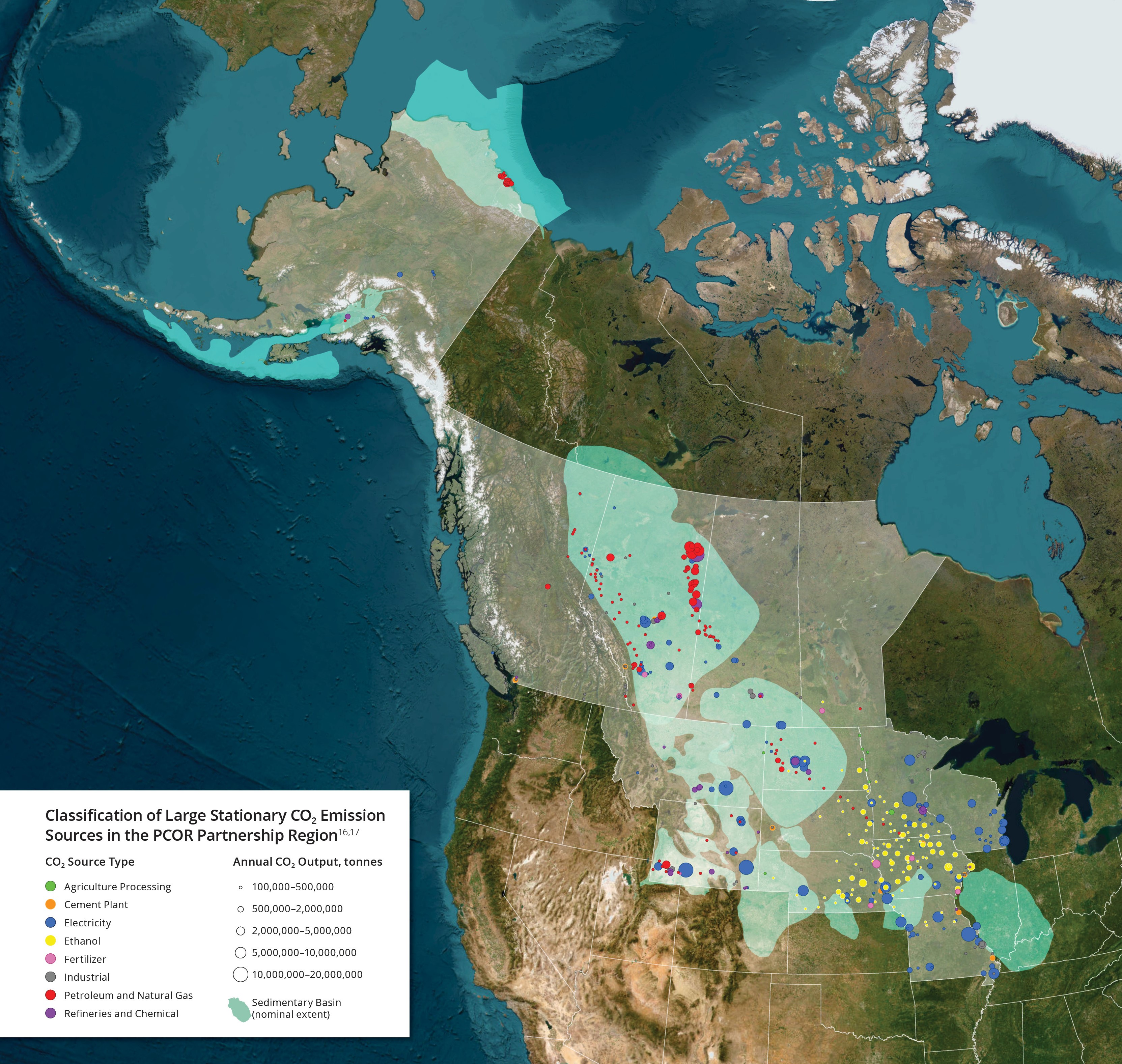
Sources by Type
The geographic and socioeconomic diversity of the PCOR Partnership region is reflected in the diversity of the CO2 sources found there. About two-thirds of CO2 is emitted from electricity generation. Significant emissions also result from energy exploration and production activities; agricultural processing; fuel, chemical, and ethanol production; and various manufacturing and industrial activities.
Canadian emissions within the PCOR Partnership region are primarily in Alberta, with extensive use of fossil fuel resources. When compared to total U.S. CO2 emissions, the states in the PCOR Partnership region emit relatively more CO2 from electric utilities and less from industries and transportation.
Although the CO2 emissions from the individual PCOR Partnership point sources are no different from similar sources located around North America, the wide range of source types within the PCOR Partnership region offers the opportunity to evaluate the capture, transport, and storage of CO2 in many different scenarios.
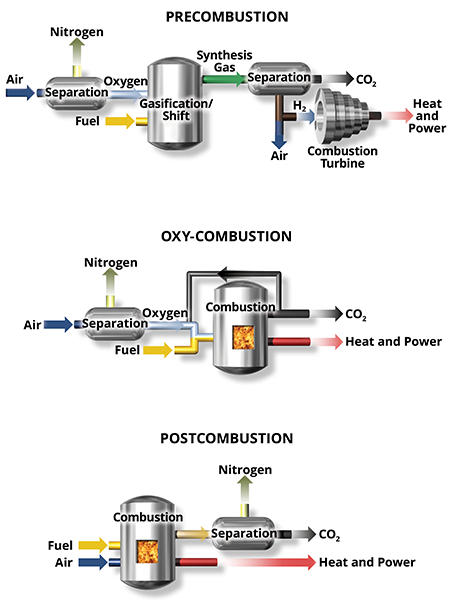
Capture at Combustion Facilities
Capture is the separation of CO2 from a gas stream to prevent atmospheric release. Capture can be performed before, during, or after the combustion process.
Precombustion technologies consist of capturing CO2 in conjunction with either gasification or methane reforming to produce hydrogen for use in a turbine.
Capture during combustion is possible when the oxygen source is pure oxygen rather than air (called oxy-combustion or oxy-fuel combustion).
The majority of capture technologies focus on separating low-concentration CO2 from the exhaust gas stream after combustion takes place; this is called postcombustion capture. This technique is the most common for retrofitting existing systems.
CO2 makes up a relatively small fraction of the exhaust gas mixture, but at a utility or industrial scale, the amount of CO2 can be quite large. Because it involves complex chemistry and specialized equipment, capturing CO2 is expensive.
Compression
Captured CO2 must be dehydrated and compressed into a supercritical state before transport to the storage site. CO2 must be compressed to at least 1200 to 1700 pounds per square inch (psi) for transport in a pipeline to ensure that CO2 remains in a dense liquid state. Because compression is energy-intensive, improved compression methods are under development.
Separation in a Postcombustion System
First, pollutants such as sulfur oxides and nitrogen oxides, as well as particulate, are removed. Even though it adds cost to the process, their removal means that the gases emitted from the stack are cleaner.
Next is the actual separation of CO2 from the exhaust gas. This is usually done by absorbing the CO2 in a liquid called a solvent and then heating the CO2-laden solvent to remove the CO2. The solvent is cooled and reused in a continuous process. The nearly pure CO2 stream is saturated with water. The water is removed from the CO2 stream to protect transport, storage, and other infrastructure from corrosion.
Once dry, the CO2 is compressed to a dense phase (much like a liquid) for transport.
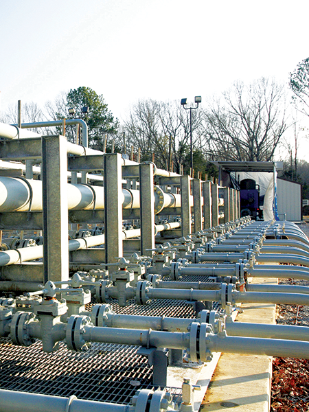
Transport
Captured CO2 must be dehydrated and compressed into a supercritical or liquidlike state for either truck transport or piping to the storage site. CO2 must be compressed to at least 1200 to 1500 psi for transport in a pipeline to ensure that it remains in a dense state. Because compression is energy-intensive, improved compression methods are under development.
Following capture and compression, CO2 is transported to a storage site. Given the quantities of CO2 that are likely to be captured from industrial sources, pipelines are the most efficient mode for transporting the captured gas to geologic storage sites.
At the supercritical state, CO2 has low viscosity like a gas and high density like a liquid. In this state, CO2 can most efficiently be pumped, injected, and stored deep underground because the CO2 occupies a much smaller space in the supercritical state than it does as a gas.
Site Selection
Picking the right geologic location is critical to the safe, permanent storage of CO2. Successful storage requires that the CO2 stays in the injection layer, also known as the storage layer. Important factors in identifying appropriate storage reservoirs include:
Capable of storing large quantities of CO2 permanently.
Thick, laterally continuous seals or cap rocks that prevent upward migration of CO2.
No geologic faults in the surrounding rocks.
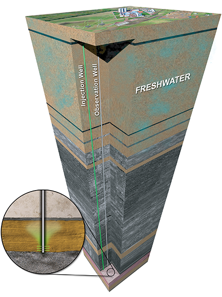
Ample barriers between the storage zone and sources of drinking water (typically deeper than 3000 feet [~800 meters]).
Rock content compatible with CO2 injection and storage.
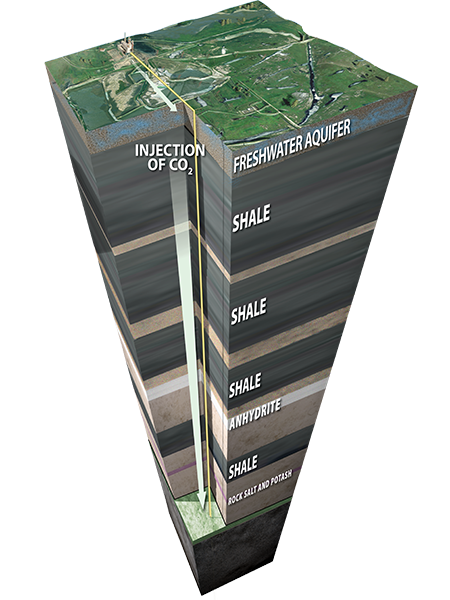
Storage
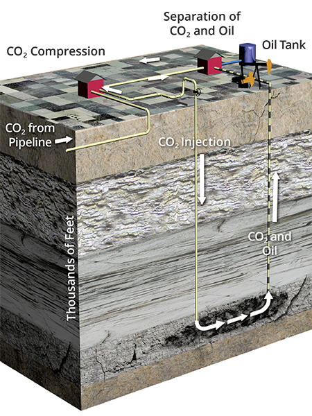
Geologic storage involves injecting captured anthropogenic CO2 into deep underground geologic formations. Permanent storage can occur in either dedicated storage projects or through enhanced oil recovery (EOR) efforts.
When CCUS projects are designed for dedicated storage, CO2 is injected into a carefully selected storage formation to permanently store it underground. When CCUS occurs as part of an EOR project, the CO2 is injected into an existing oil-bearing reservoir to increase oil production. A portion of the CO2 will be brought back to the surface with the oil where it is then separated and reinjected into the same reservoir.
During the life cycle of the EOR process, nearly 100% of the purchased CO2 becomes trapped in the reservoir, a secondary benefit that produces oil with a smaller carbon footprint.
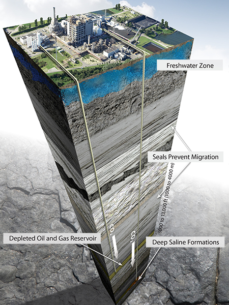
Storage in Formations
Many suitable areas across the globe have the capacity to hold CO2 emissions safely and securely deep underground. These formations exist in sedimentary basins and include oil and gas fields and saline formations. What these formations have in common is a porous and permeable storage layer sealed by impermeable cap rocks.
Oil fields have many characteristics that make them excellent target locations to store CO2. The geologic conditions that are conducive to hydrocarbon accumulation are also the conditions that are conducive to CO2 storage.
The three requirements for trapping and accumulating hydrocarbons are a hydrocarbon source, a reservoir layer with connected pore space to allow flow and storage, and impermeable seals—cap rocks above the reservoir that prevent escape.
A single oil field can have multiple zones of accumulation, i.e., oil reservoirs and more than one depth.
Like oil, supercritical CO2 is lighter than the ancient ocean water in the oil reservoir. Injection pushes the CO2 outward from the well to flow upward through the tiny paths between rock grains until the CO2 reaches an impermeable seal. In an EOR operation, the CO2 will mix with any oil it encounters, swelling and mobilizing more oil for production. In the long term, the CO2 will dissolve into the formation fluids and eventually mineralize, becoming part of the formation rock.
Sedimentary basins are relatively large areas of Earth’s surface that have subsided over long periods of geologic time, allowing for the accumulation of sediments that eventually lithified into rock. Areas where the accumulation of sediments is thick enough (>800 meters) may have an arrangement of rock layers suitable for CO2 storage. Many sedimentary basins are home to hydrocarbon accumulations that are being tapped in oil and gas fields worldwide.
Most rock layers in sedimentary basins do not have a hydrocarbon source but are often saturated with brine. These layers are called saline formations and are widely distributed throughout North America and the rest of the world. Their geologic characteristics, global spread, and proximity to many large-scale CO2 sources mean deep saline formations account for most of the world’s geologic storage resource. They also provide an ideal storage option for facilities not able to take advantage of economic CO2 EOR opportunities.
Saline formations suitable for CO2 storage comprise sandstone, limestone, dolomite, or some mix of the three. Many of these formations are ideally situated to provide great potential for CO2 storage and are also overlain by thick and regionally extensive cap rocks, typically shales and salts. These cap rocks function as seals to help ensure that the injected CO2 remains in place permanently.
Monitoring, verification, and accounting (MVA) are used to monitor the site before, during, and after CO2 injection operations occur.
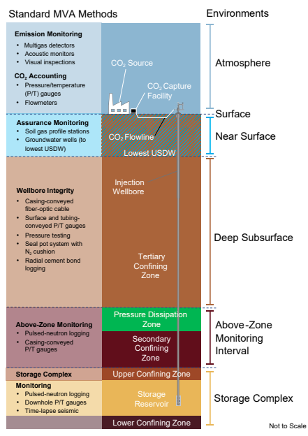
Monitoring
Monitoring, verification, and accounting (MVA) technologies and techniques are used to track the migration of injected CO2 as well as to confirm that the surface and subsurface environments are not negatively impacted by injection activities. A variety of monitoring technologies can be implemented before, during, and after injection operations, in the surface, near-surface, and deep subsurface environments at a CO2 storage site.
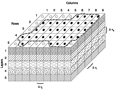
Modeling & Simulation
A geologic model is a computerized 3D rendering of the subsurface that provides a digital framework of the CO2 reservoir complexities, critical to understanding CO2 storage. The components of geologic models help provide predictions that are important for the design of a CO2 storage system, assessment of the project risks, and the design and interpretation of the results of a monitoring and accounting program.